Digital System Design
RISC-V datasheet: (https://pipirima.top/2022-2023/RISC-V-green-card-d1b1771d8486/riscvcard.pdf)
Architecture
Von Neumann:
normally programe code and memory are saved in same RAM, hence only one bus will be used and translate programe and memory together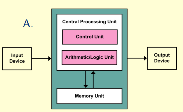
Harvard:
seperate programe and memeory apart, can use multiple bus groups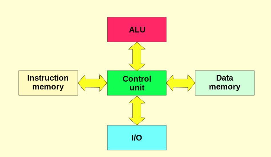
Modified harvard:
merge two bus groups (memory and instruction) into one, but still save memory and programe into different structure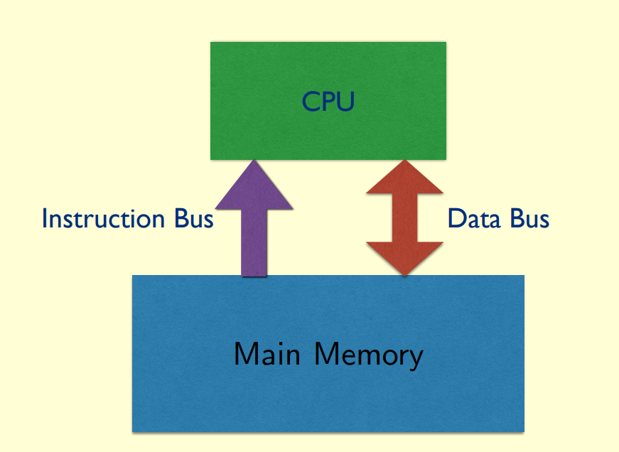
Clock time calculation

• Clock period (clock cycle time)
• Clock frequency (Clock Rate) = 1/Clock period
• Clock Cycle Time = 1/Clock rate
• CPU Time = Clock Cycles * Clock Cycle Time
• Clock Cycles = Instruction Count * Cycles per Instruction (CPI)
note: final clock cycles is their sum result if there have multiple IC and CPI
• MIPS = Clock Rate / (CPI * 10e6)
Risc V code
Basic synax


note: most of instructions are based on signed number
| Name | Descripetion |
|---|---|
| opcode | operation code |
| rd | destination register number |
| funct3 | 3-bit function code (additional opcode) |
| rs1 | the first source register number |
| rs2 | the second source register number |
| funct7 | 7-bit function code (additional opcode) |
RISC-V (RV32) has a 32 × 32-bit register file in Little Endian
32-bit data is called a “word” in RV32
normally we can use temporaries registers freely
|register|usage|
|:—-|:—-|
|x0|the constant value 0|
|x1|return address|
|x2|stack pointer|
|x3|global pointer|
|x4|thread pointer|
|x5 – x7, x28 – x31|temporaries|
|x8|frame pointer|
|x9, x18 – x27|saved registers|
|x10 – x11|function arguments/results|
|x12 – x17|function arguments|
R type
add x9,x20,x21
| funct7 | rs2 | rs1 | funct3 | rd | opcode |
|---|---|---|---|---|---|
| 0 | 21 | 20 | 0 | 9 | 51 |
| 7 bit | 5 bit | 5 bit | 3 bit | 5 bit | 7 bit |
| 000 0000 | 1 0101 | 1 0100 | 000 | 0 1001 | 011 0011 |
I type
lw x9,32(x22) -> load X9 by the data from x22[8] //32 byte/4 = 8 words
| immediate | rs1 | funct3 | rd | opcode |
|---|---|---|---|---|
| 32 | 22 | 2 | 9 | 3 |
| 12 bit | 5 bit | 3 bit | 5 bit | 7 bit |
| 0000 0010 0000 | 1 0110 | 010 | 0 1001 | 000 0011 |
S type
sw x9,32(x22) -> save x9’s data into x22[8]
| imm[11:5] | rs2 | rs1 | funct3 | imm[4:0] | opcode |
|---|---|---|---|---|---|
| 1 | 9 | 22 | 2 | 0 | 23 |
| 7 bit | 5 bit | 5 bit | 3 bit | 5 bit | 7 bit |
| 000 0001 | 0 1001 | 1 0110 | 010 | 0 0000 | 001 0111 |
imm=32=0000 0010 0000
U type
lui x19, 976
| Immediate [31:12] | rd | opcode |
|---|---|---|
| 976 | 19 | 55 |
| 20 bit | 5 bit | 7 bit |
| 0000 0000 0011 1101 0000 | 1 0011 | 011 0111 |
note: U type can read upeer 20 bits from register, if some data is in total 32 bits
SB type
bne x10, x11, 2000
| Imm [12] | Imm [10:5] | rs2 | rs1 | funct3 | Imm [4:1] | Imm [11] | opcode |
|---|---|---|---|---|---|---|---|
| 0 | 62 | 11 | 10 | 1 | 8 | 0 | 51 |
| 1 bit | 6 bit | 5 bit | 5 bit | 3 bit | 4 bit | 1 bit | 7 bit |
| 0 | 11 1110 | 0 1011 | 0 1010 | 001 | 1000 | 0 | 110 0011 |
imm=2000=0111 1101 0000
Target address = PC + immediate
eg. if this code is in address X20, new jumped add=20+2000=x2020
UJ type
jal x1, 2000
| Imm [20] | Imm [10:1] | Imm [11] | Imm [19:12] | rd | opcode |
|---|---|---|---|---|---|
| 0 | 62 | 0 | 0 | 1 | 111 |
| 1 bit | 10 bit | 1 bit | 8 bit | 4 bit | 7 bit |
| 0 | 11 1110 1000 | 0 | 0000 0000 | 0 0001 | 110 1111 |
imm=2000=0111 1101 0000
basic srchitecture structure
- load data from memory to register
- save result from register to memory
Registers are faster to access than memory

each operation will only part of these terminals


Zero in ALU is result of comparation
| instruction | Branch | MemRead | MemtoReg | ALUOp | MemWrite | ALUSrc | RegWrite |
|---|---|---|---|---|---|---|---|
| R_type | 0 | 0 | 0 | 10 | 0 | 0 | 1 |
| load | 0 | 1 | 1 | 10 | 0 | 1 | 0 |
| save | 0 | 0 | x | 00 | 1 | 1 | 0 |
| beq | 1 | 0 | x | 01 | 0 | 0 | 0 |
pseudoinstruction
| name | format | description | used instruction |
|---|---|---|---|
| mv | mv rd, rs | R[rd] = R[rs] | addi |
| li | li rd, immed | R[rd] = immed | addi |
| la | la rd, addr | R[rd] = addr | auipc |
| neg | neg rd,rs | R[rd]=-R[rs] | sub |
| not | not rd, rs | R[rd]=~R[rs] | xori |
pipeline
pipeline can increase programe ratio
RISC-V can use upper 5 levels:
| step | name | descreption | time |
|---|---|---|---|
| 1 | IF | Instruction fetch from memory | 200ps |
| 2 | ID | Instruction decode & register read | 100ps |
| 3 | EX | Execute operation or calculate address | 200ps |
| 4 | MEM | Access memory operand | 200ps |
| 5 | WB | Write result back to register | 100ps |


Data Harzard:
An instruction depends on completion of data access by a previous instruction
Load-Use Data Hazard:
Please note that instructions following a branch require a 1-step interval to wait for the result of the branch.
but we can predict the result, and correct it immediate if not right
CISC and RISC
| RISC | CISC |
|---|---|
| Reduced Instruction Set Architecture | Complex Instruction Set Architecture |
| low cycles per instruction | hign cycles per instruction |
| Simpler instruction | Complex instruction |
| Fewer Data types | More Data types |
| Pipline canbe achieved | / |
memory
| device | response time | cost |
|---|---|---|
| Static RAM | 0.5ns – 2.5ns | $500 – $1000 per GiB |
| Dynamic RAM (DRAM) | 50ns – 70ns | $3 – $6 per GiB |
| Flash SSD | 5 µs - 50 µs | $0.06 – $0.12 per GiB |
| Magnetic disk | 5ms – 20ms | $0.20 – $2 per GiB |
normally SRAM and DRAM are used in memory,
SSD and disk are used in storage
Binary Notation: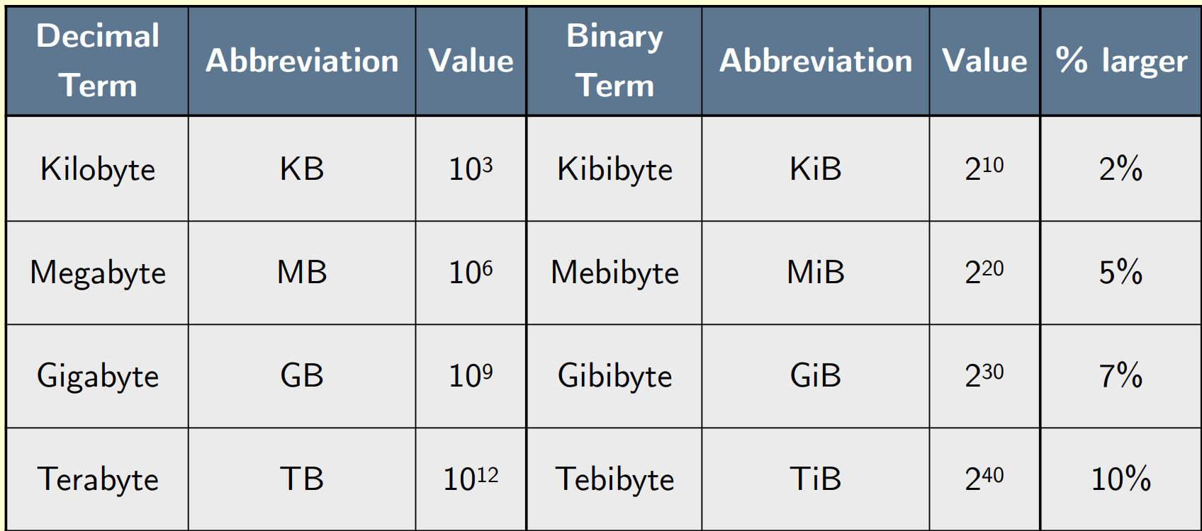
Locality
Temporal locality:Items accessed recently are likely to be accessed again soon
Spatial locality: Items near those accessed recently are likely to be accessed soon
result:
Memory hierarchy
Store everything on disk
Copy recently accessed (and nearby) items from disk/DRAM to smaller DRAM/more smaller DRAM memory
cache
The level/s of the memory hierarchy closest to the CPU
Direct Mapped Cache: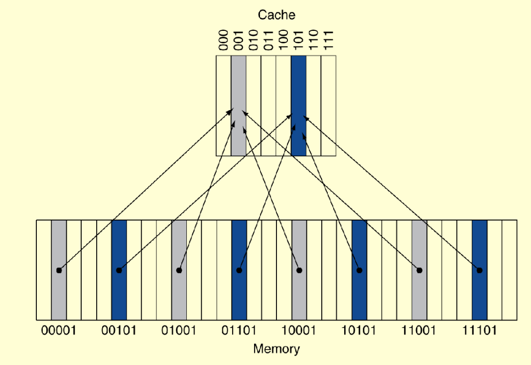
binary address = {Tag, Index}
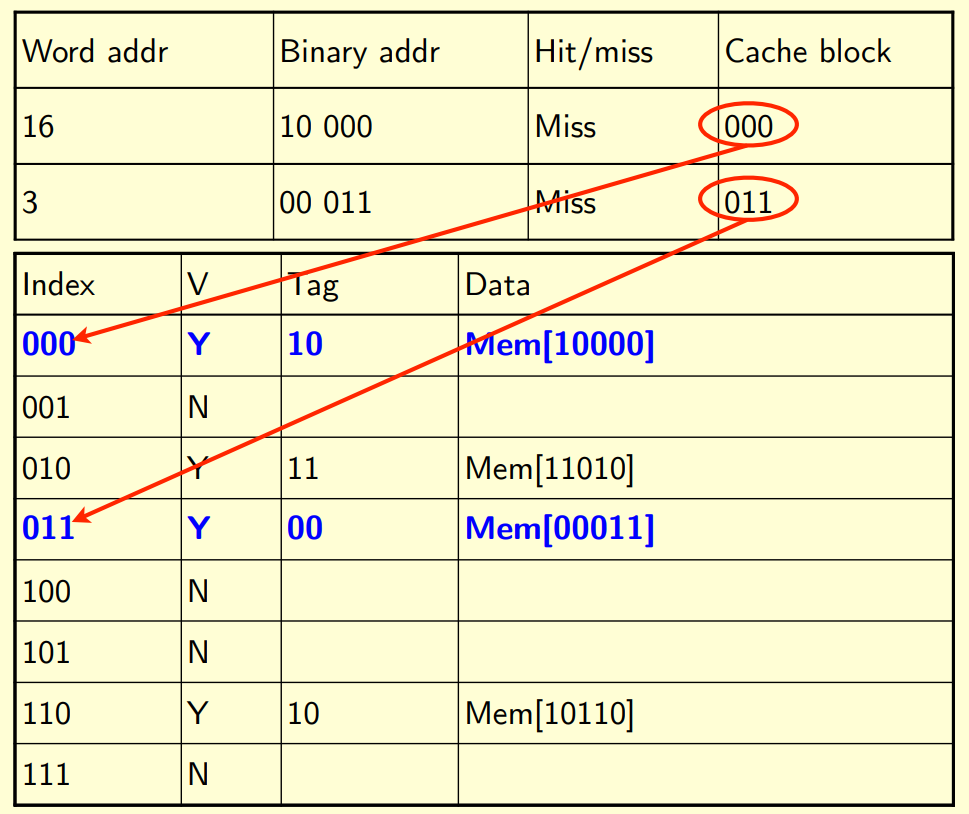
if the address is already saved, Hit/Miss will be hit. otherwise will be miss
hit will be marked only when both tag and index are fit
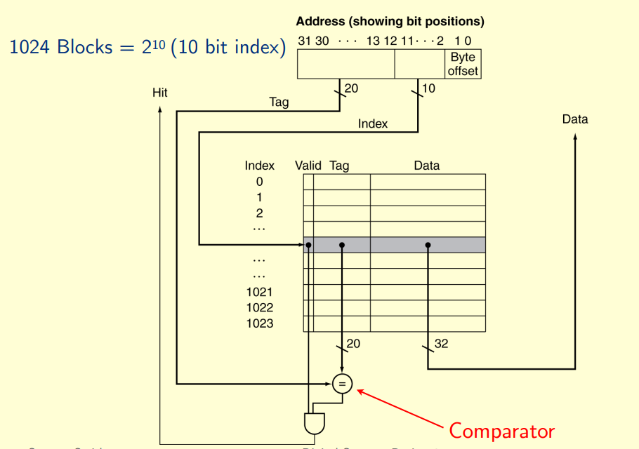

index: determine which line
Tag: determine whether has saved
Block offset: determine which word in this address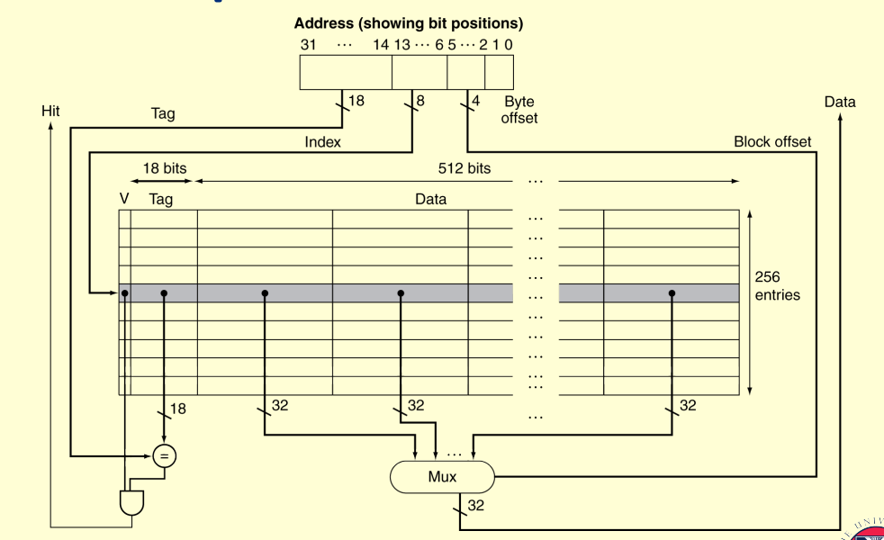
Very large blocks mean fewer blocks in cache and an increased miss rate
Large blocks also increase the miss penalty of retrieving the block from the next level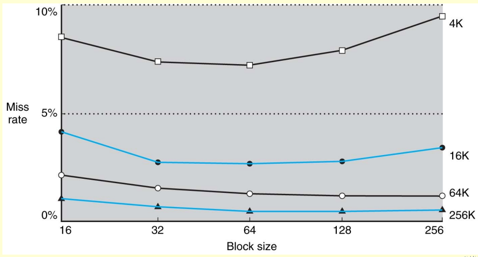
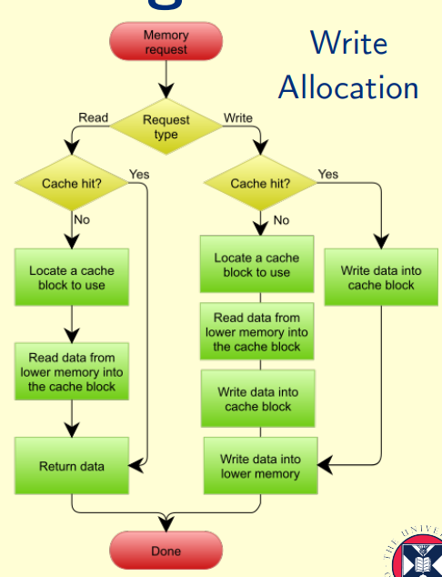
cache performance
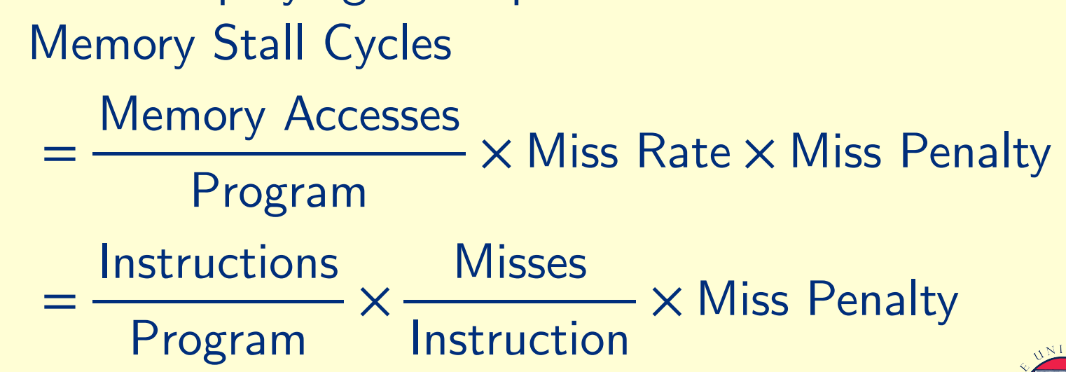

Average memory access time
AMAT = Hit time + Miss rate × Miss penalty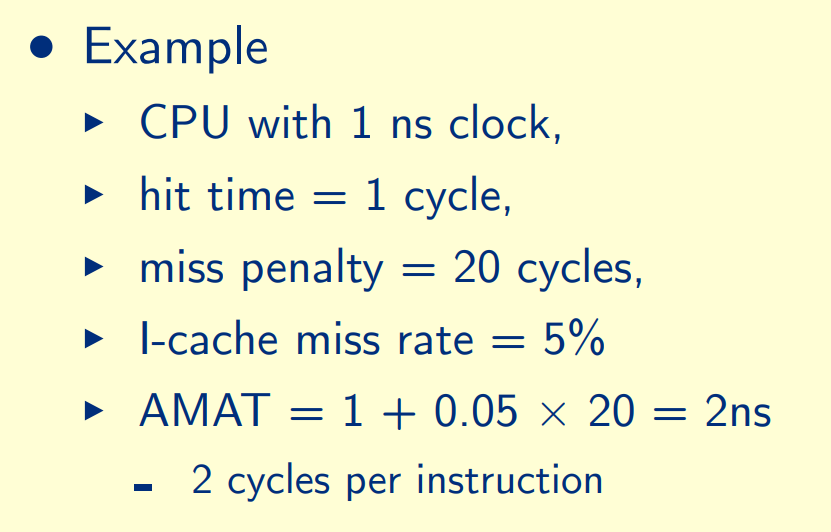
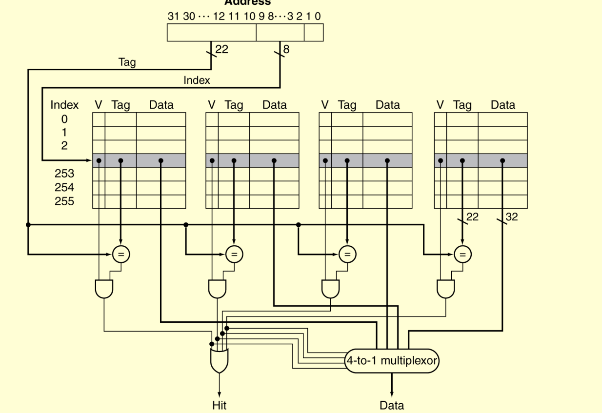
n-set Associativity
Higher associativity reduces miss rate
Increases complexity, cost, and access time
4-block caches:
Index = (Block address) % (number of entries)
like: 8 % 4 = 0
6 % 4 = 2
hence mem[8,0] saved in index 0,
mem[6] saved in index 2.
read data inorder 8, 0, 8, 6, 8:
2-way set associative:
Index = (Block address) % (number of entries)
read data in order of : 8, 0, 8, 6, 8: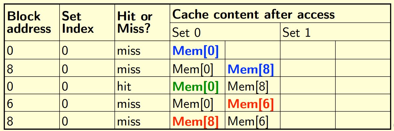
note: if a new data want be saved in a full set(like in row 4), the last-used data will be removed(mem[0] is remained)
Fully associative (8-way):
Blocks can go anywhere
read data in order of : 8, 0, 8, 6, 8:
address bit allocation
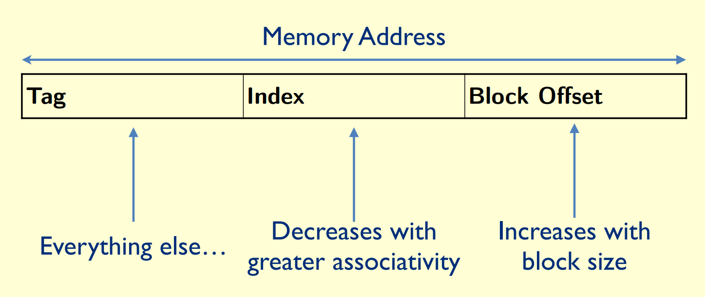
Block size is defined by the offset bits
blocks/lines is defined by index
If we have a directly mapped cache of size 1 KiB with block size of 4 words, 32 bits address
each block has 4 word * 4 bytes = 16 bytes, block offset is 4 bits
total block number = 1kiB/16bytes = 64 blocks per set, index is 6 bits
the tag is 32 - 4 - 6 = 22 bits
if we have a 4-way set associative instruction cache,
total block number = 1kiB/(16bytes * 4) = 16 blocks per set, index is 4 bits
Block_size = word_number * 4 bytes
block_number = cache_size / block_size
index_number = block_number / n_way
| miss rate | hit time | miss penalty | |
|---|---|---|---|
| associativity of a cache is increased | Decreased | Increased | No expected change |
| block size of a cache is decreased | Increased | No expected change | Decreased |
virtual memory
Each gets a private virtual address space holding its frequently used code and data and Protected from other programs
VM “block” is called a page
VM translation “miss” is called a page fault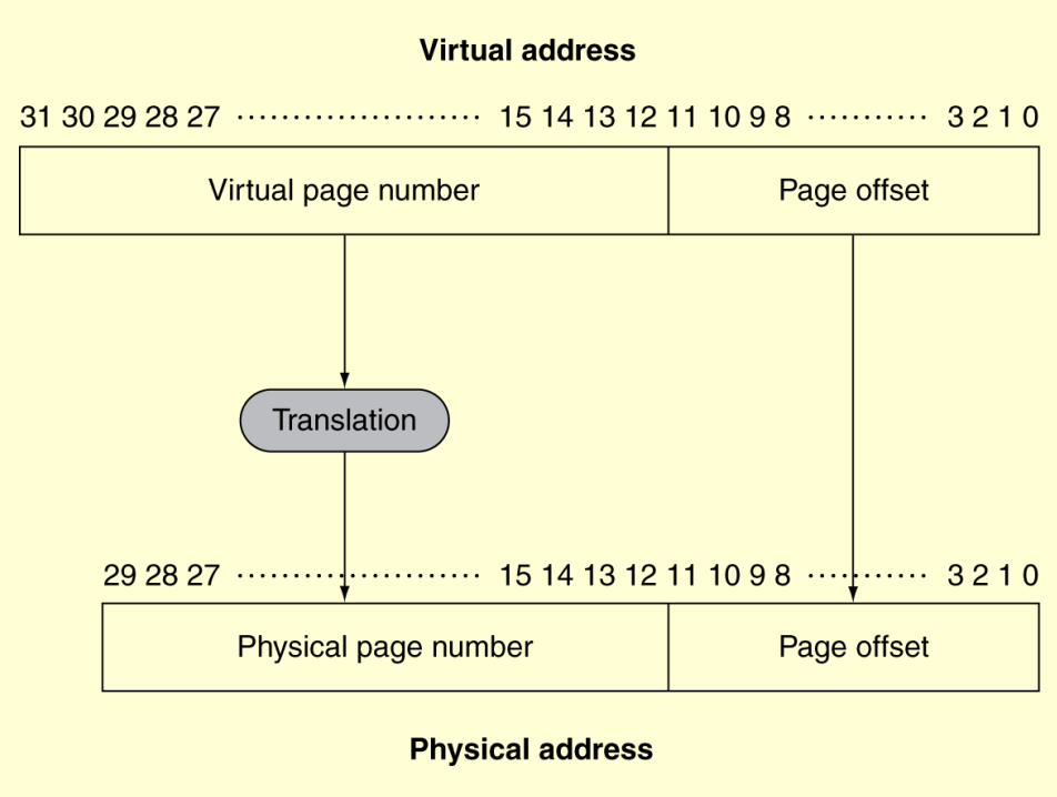
Translation Using a Page Table: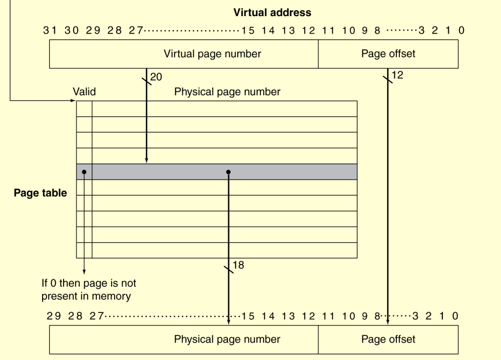
if valid is 1, data is saved in physical memory
if valid is 0, data is saved in disk
Translation Look-aside Buffer (TLB)
the last visited entry block will be replace with new data
if new tag is miss in TLB: TLB MISS
if new tag exist in page table: PT HIT
if new tag in page table is only in disk: PAGE FAULT
parallel
Multiple Issue
Static Multiple Issue: Group of instructions that can be issued on a single cycle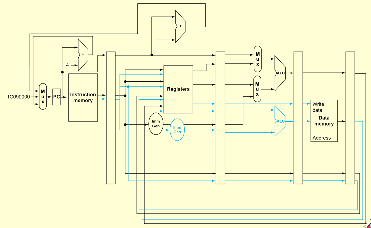
One ALU/branch instruction, One load/store instruction run together
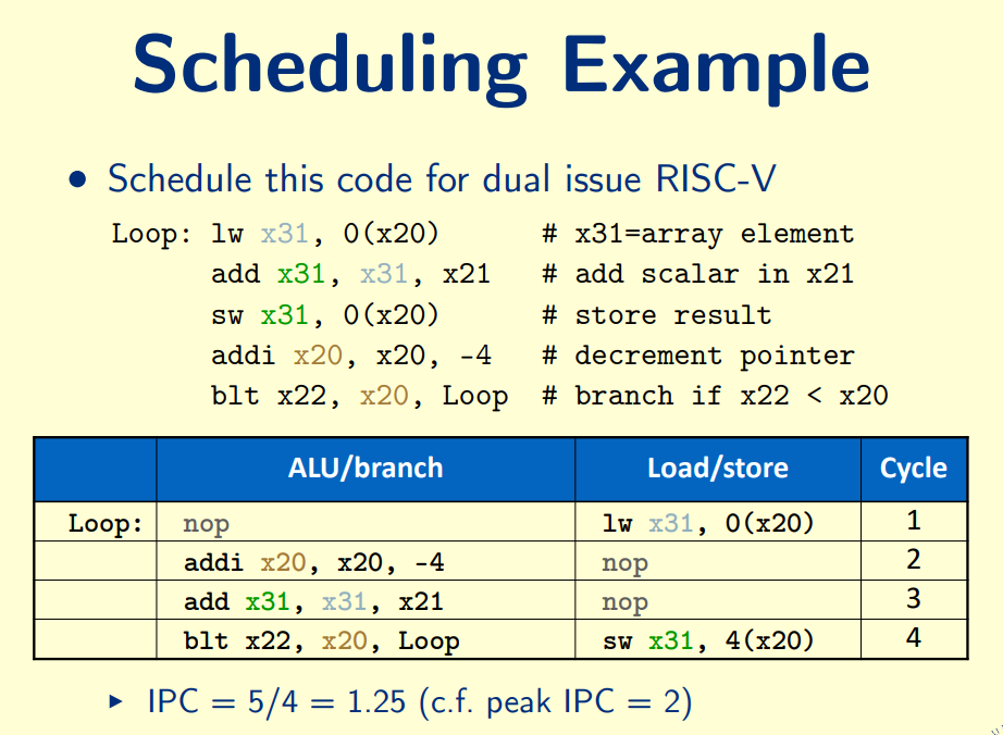
Dynamic Multiple Issue: Allow the CPU to execute instructions out of order to avoid stalls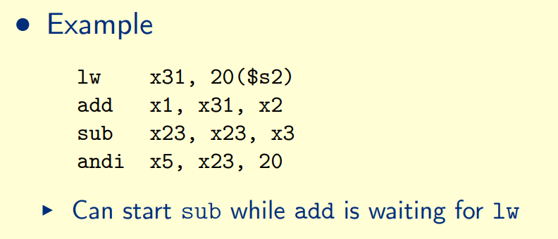
speed up
T1 = time to run with one worker
TP = time to run with P workers
T1/TP = speedup (Ideal case is linear speedup with P)
T1/(P*TP) = efficiency (Ideal case is efficiency is 1)
Amdahl’s Law
Tsequential + Tparallel/P ≤ TP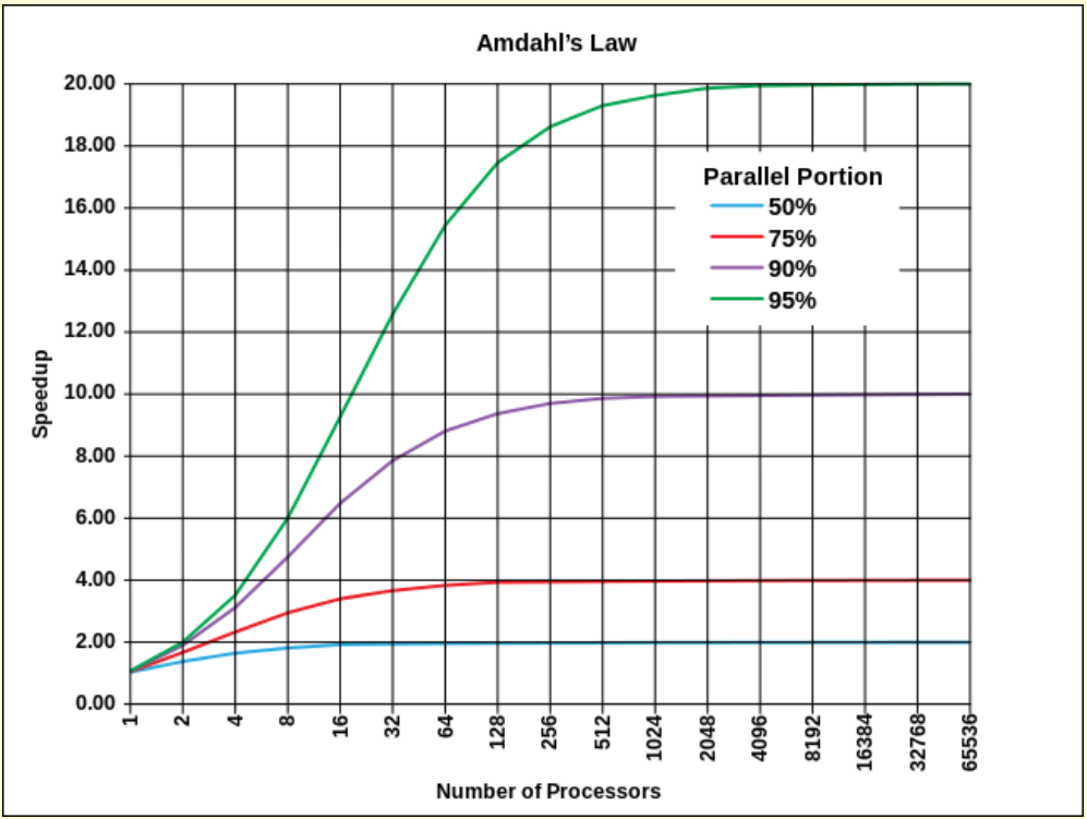
if 100 processors, 90× speedup
if sum of 10 scalars, and 10×10 matrix sum,
Time = (10 + 100) × tadd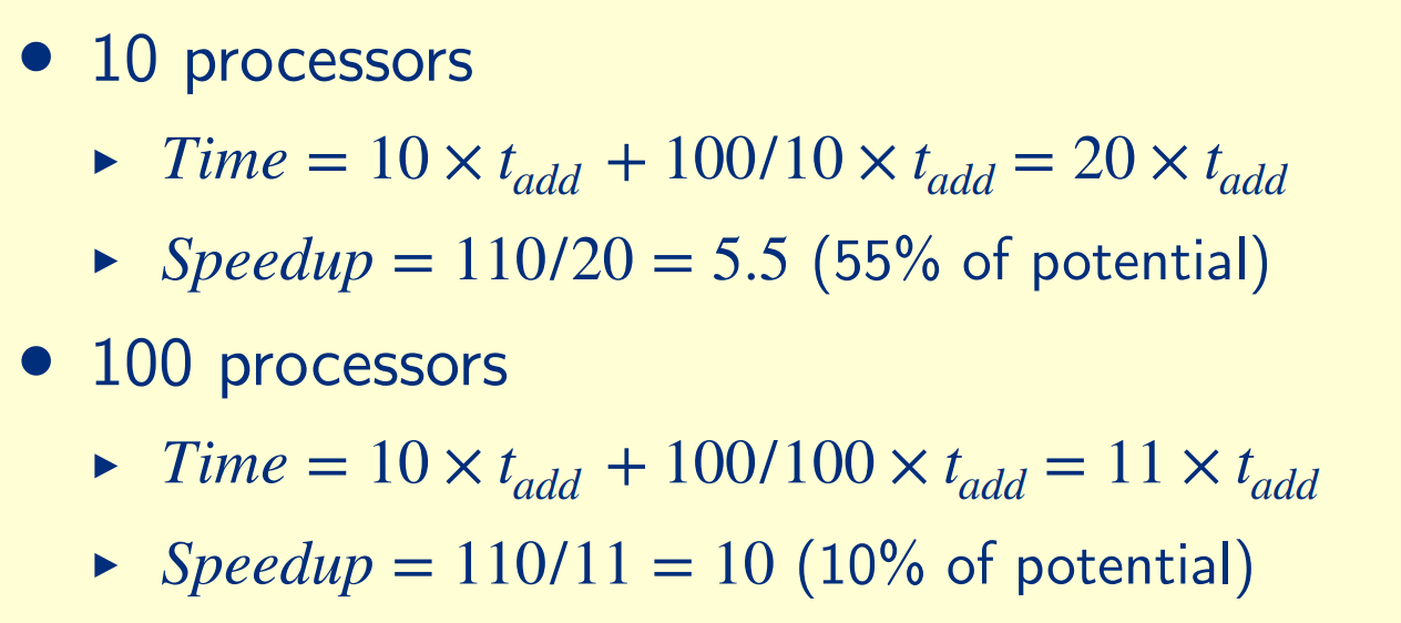
Strong scaling: problem size fixed
Weak scaling: problem size proportional to number of processors
If 100 processor, one processor has 2% load not 1%
Shared Memory Multiprocessors
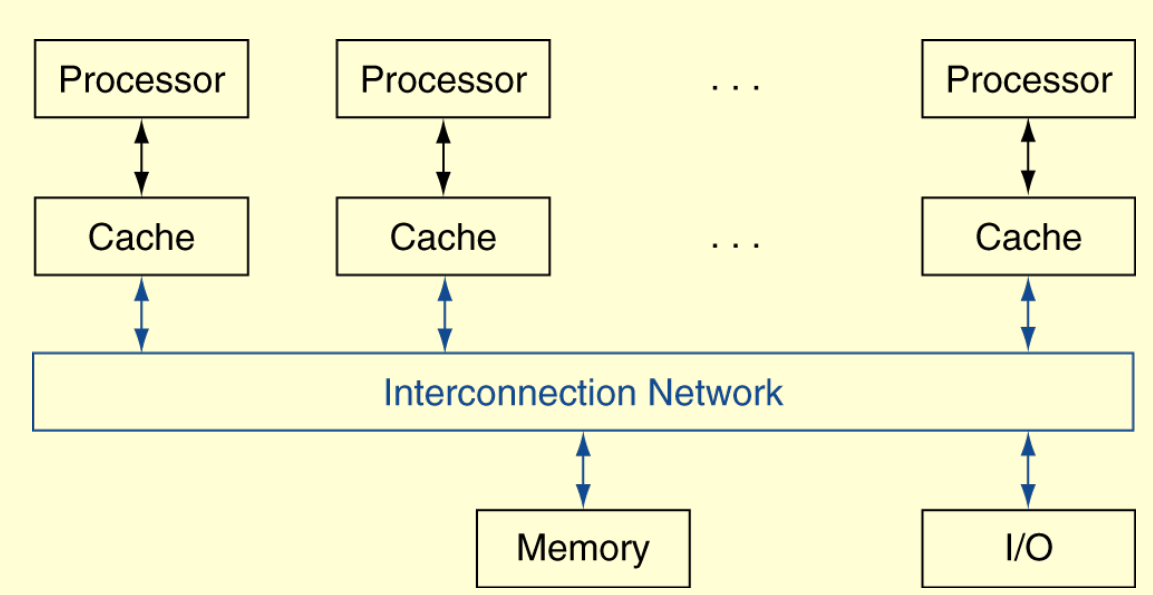
UMA (uniform) vs. NUMA (nonuniform)
if 1 GiB total memory, 40 cycles/word
NUMA 2 processors: 512 MiB local memory each, 20 cycles/word to local, 60 cycles/word to remote memory
UMA 2 processors: 1 GiB shared memory, 40 cycles/word
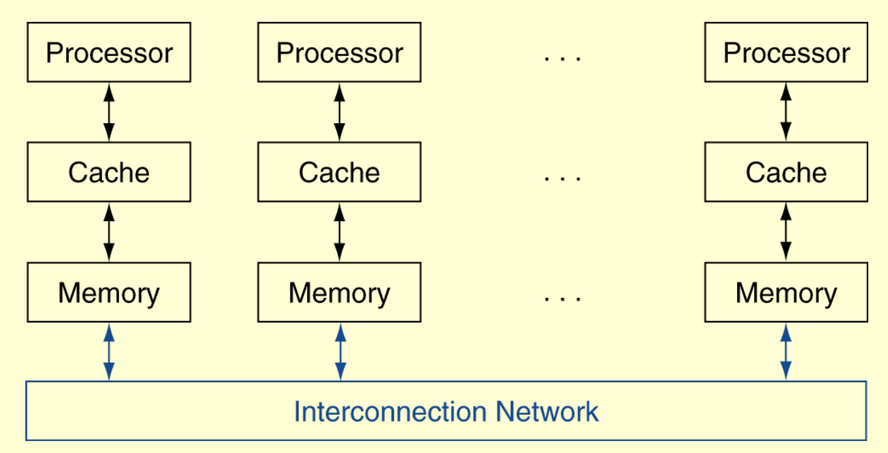
Message Passing
Multithreading
Fine-grain multithreading: If one thread stalls, others are executed
Coarse-grain multithreading: Only switch on long stall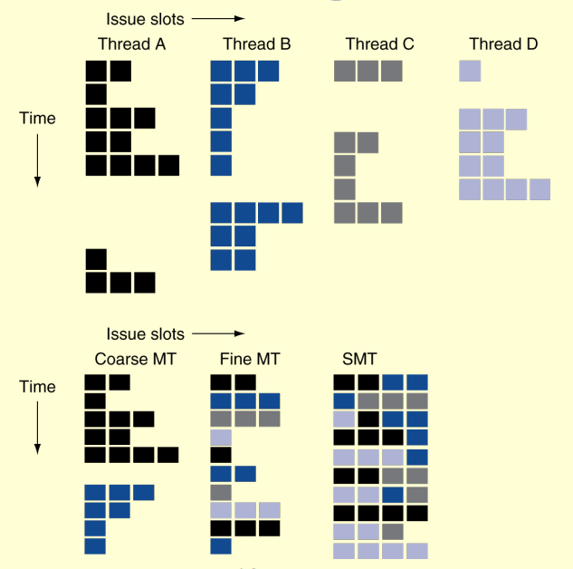
Flynn’s Taxonomy
Single Instruction Single Data (SISD)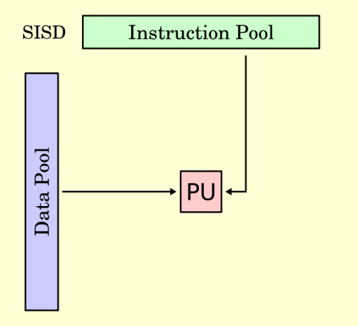
Single Instruction Multiple Data (SIMD)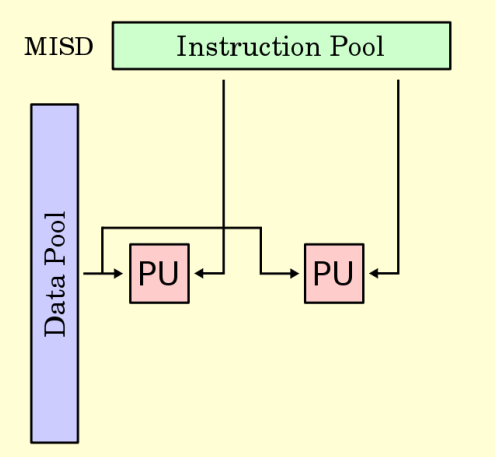
Multiple Instruction Single Data (MISD)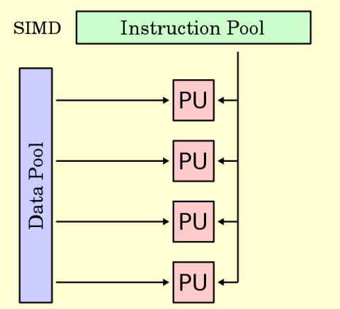
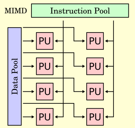
Multiple Instruction Multiple Data (MIMD)